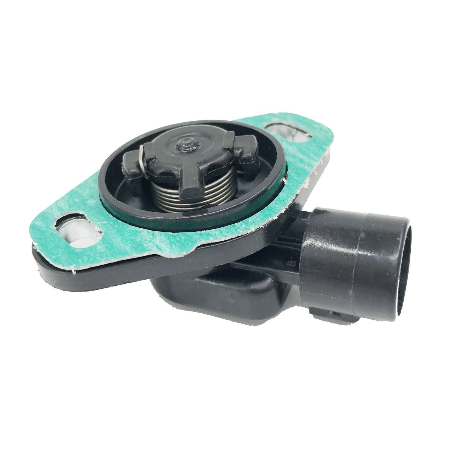
TPS(Throttle Posision Sensor) design pt.1
Welcome to part 1 of a series of blog posts.
What in the world is a TPS?⌗

For some context a TPS is a throttle position sensor. This is used by car manufactures to tell exactly how far down you’ve pressed the throttle pedal.
The specific part I’m working on designing a replacement for is a TPS sensor for a Honda Civic with a D-series engine.
The OEM sensor itself is a very simple design, housing a analog potentiometer inside of a plastic housing.
The sensor itself has only three connections, VCC at 5v, GND, and a tps signal that goes between 0.45v-4.5v during operation.
Why is a whole new design needed?⌗
This is where things get a bit more complicated. The original design used decent quality components and this meant that the potentiometer itself stayed in a usable state for some 20 years.
Issue is that almost no-one manufactures the part in a decent quality, with existing manufactures offerings falling apart or wearing through the resistive material internally so quickly that they will often last less than a year.
Design Criteria⌗
With all this in mind I came up with a list of requirements for the replacement.
Requirements:
- No critical mechanical wear surfaces.
- Reliable and tunable system.
- Low cost of materials.
- Powered off existing connection.
Component selection⌗
Breaking down the requirements as simply as possible, I needed a way to measure the angle or position of a shaft, map that to an appropriate voltage and send the signal to the ECU.
This list gave me the following basic outline:
- micro-controller
- magnetic rotary encoder
- DAC(Digital To Analog Converter)
My original plan was to try and create the system using as few components as possible. As the design progressed however I found myself realizing that the cost of a microcontroller that could preform the DAC functions needed would cost more than a lower cost micro-controller and stand alone DAC.
Magnetic Encoder⌗
For the magnetic encoder I only needed to actually track a small range of approximately ninety degrees. This also didn’t have a very strict requirement for how fast the sample rate needed to be given the low speeds or rotation.
For this I selected the AS5600 IC.
Spec Summary:
- 12bit resolution, 4096 values.
- I2C interface.
- 5v/3.3v power input.
- -40C-125C temperature range.
Given the specifications it’s more than adequate for working inside of a hot engine bay.
DAC(Digital To Analog Converter)⌗
The MCP4725 IC from MicroChip was an easy choice given it’s availability and low cost.
Spec Summary:
- 12bit resolution.
- I2C interface.
- Single channel.
- 5v/3.3v output.
- -40C-125C temperature range.
Micro-Controller⌗
The selection of micro-controller is a bit different than the other components.
I selected the ch32v203 series of controllers for their low cost and interesting set of peripherals. I also considered the ch32v003 and stm32103 but ultimately decided I wanted to explore using a different architecture.
Spec Summary:
- RISC-V QingKe V4 Core
- 144MHZ clock rate.
- 64KB Flash
- 2x I2C
- 4x USART
- 2x SPI
- 1x CAN
- 1x RTC
- ….and more.
Honestly the micro-controller is complete over-kill for this application In this case it’s a reasonable given it’s lower cost compared to the RP2040 and STM32 controllers with equivalent features.
I say equivalent but the RP2040 isn’t usually a controller I want to select or work with given the ADC issues, lack of built in flash as well as having no USB peripherals(PIO isn’t a substitute). Having a higher unit cost doesn’t help either although I find the dual core architecture interesting.
Schematic Design⌗
For the schematic and PCB design I used KiCAD.
Creating new Libraries⌗
New symbol and footprint libraries had to be made for the new components as the encoder and the micro-controller didn’t have any existing ones.
Continuation⌗
TO BE CONTINUED