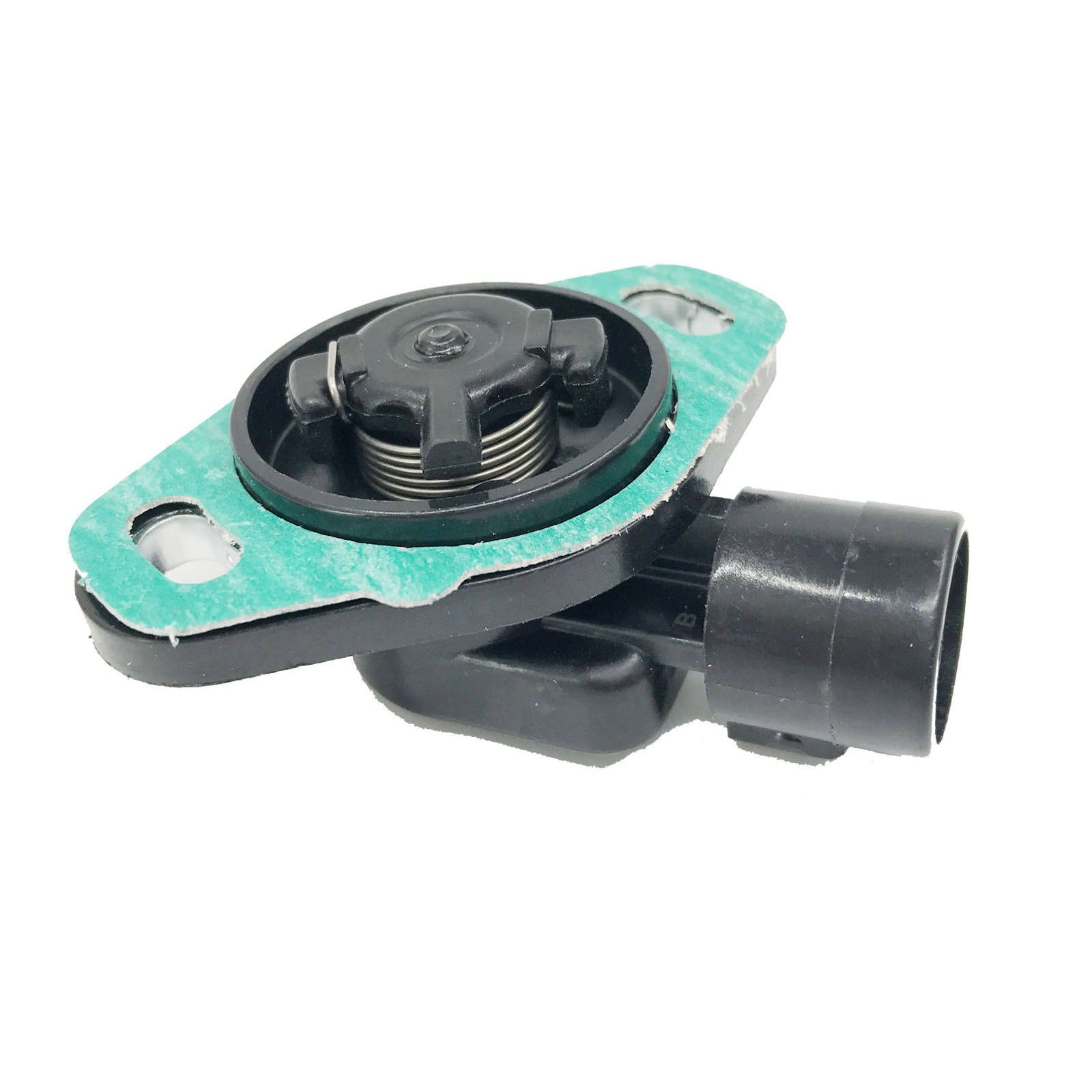
TPS(Throttle Posision Sensor) design pt.2
Reverse Engineering The OEM TPS⌗
put image of 3D modeled tps

Taking Measurements⌗
Measurements from the OEM TPS sensor were all gathered using a stainless steel metric ruler with 0.5mm marks. This means when we can get actual measurements of 0.25mm by estimating based on estimation of our eye’s when taking readings.
I took the measurements from all the available sections I could access via this method yielding enough data to begin the modeling process.
FreeCAD⌗
To start off the design process I created a spread sheet to hold all the measurements from taken earlier.
The spread sheet cells can be referenced when defining the parameters for cad models constraints. The cells offer a way to use named values that can be calculated in formulas to dynamically alter the 3D model.
The design is currently in the first revision and will still need to be changed for easier 3D printing.
Connector Woes⌗
The hardest part of the prototyping of the TPS project so far has been the electrical connection.
The connector doesn’t seem to have a well known name like many older connectors in automotive applications.
In the case particularly this connector is known to have issues where the vibration of the engine causes the solder connections attached to the pins in aftermarket units to crack and fail.
The best solution I have come up with is to create a separate connector that will allow a potted back end for the pins which will then have a cable running to the new TPS sensor itself.
This also gives the benefit of keeping the original wiring harness connectors.
Continuation⌗
In part 3 I’ll cover the schematic design and the PCB layout choices.